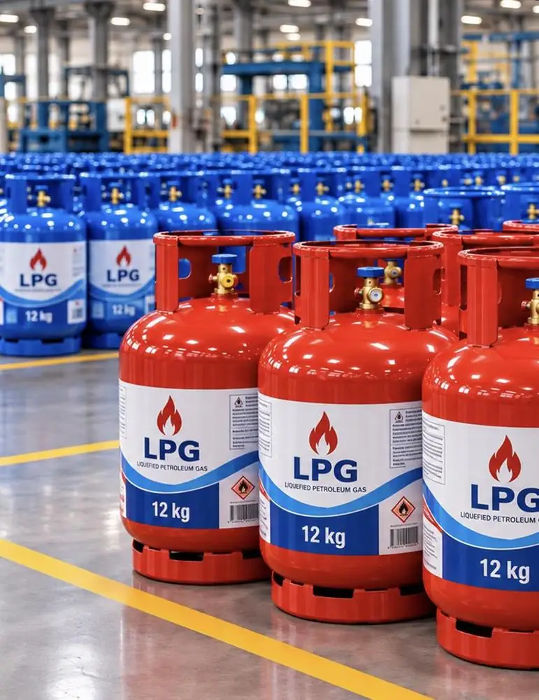

LPG cylinder filling plant
Safe. Standards-compliant. EPC+F-ready.Turnkey LPG cylinder filling plants, from bulk storage to dispatch, for 600–2,100 cylinders per hour.
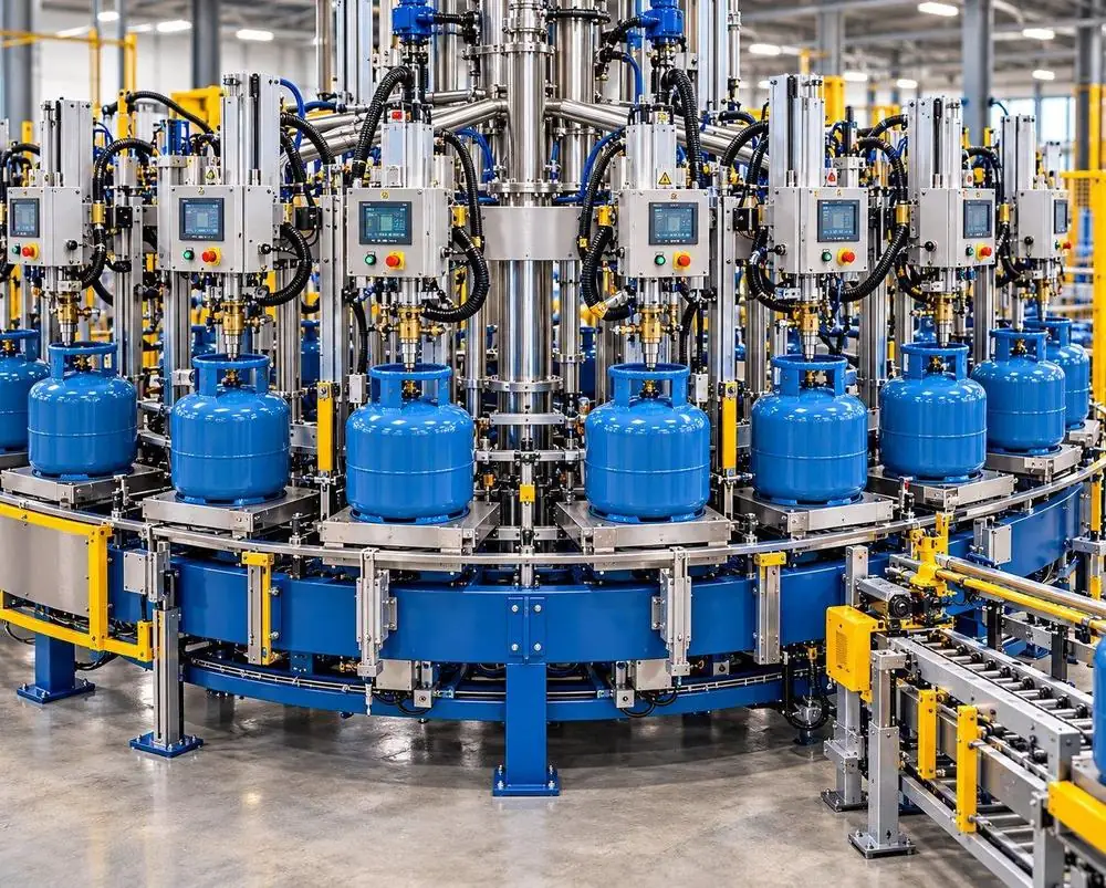
Turnkey EPC+F filling plant for domestic and commercial LPG cylinders
Cylinders per hour
12–36 carousel stations
Bulk LPG storage
Base case
Cylinder range
Domestic and commercial
Delivery model
Turnkey delivery with financing
Objective: a safe, standards-compliant and fully traceable LPG cylinder filling operation, as a new greenfield plant or the modernisation of an existing depot.
The filling concept is selected by demand, cylinder mix and available land
Containerised / skid plant
ISO tank → filling container → cylinder stock
Prefabricated modules including ISO tank; fits on about 50 × 50 m of land and can be relocated as demand grows.
In-line filling
LPG manifold → scales in series → check and leak test
Filling heads in series; manual, semi- or fully automatic, with heads added as demand increases.
Automatic carousel
Empty in → 12–36 scales → check and leak test
12–36 filling stations (larger on request), with an upgrade path from semi- to full automation.
Key drivers: demand location · cylinder and valve mix · available land · annual demand and peaks · expansion path.
Designed to the mandatory codes of the host country

ATEX 2014/34/EU
Hazardous-area zoning and certified Ex equipment for Zone 1 and Zone 2.

EN 13445 / PED
Design of storage vessels, pressure piping and relief systems (PED 2014/68/EU).

OIML R76 / EN 45501
Metrology of filling and check scales; legal-for-trade approval.
Final safety distances, zone extents and design pressures are confirmed against local regulations and the licensing authority.
One-way cylinder flow from truck unloading to dispatch
Unloading
Telescopic conveyor, 3–11 m reach
Inspection
Defects to repair or requalification
Tare check
Tare read on the conveyor
Carousel filling
By weight, automatic cut-off
Check weighing
0.1% accuracy
Correction
Rejects topped up or evacuated
Leak test
Gas detector or water bath
Seal and dispatch
Shrink sleeve, palletising, loading
Control gates: tare record → fill record → check weight → leak test → seal and dispatch.
Safe bulk receipt and transfer to the filling hall
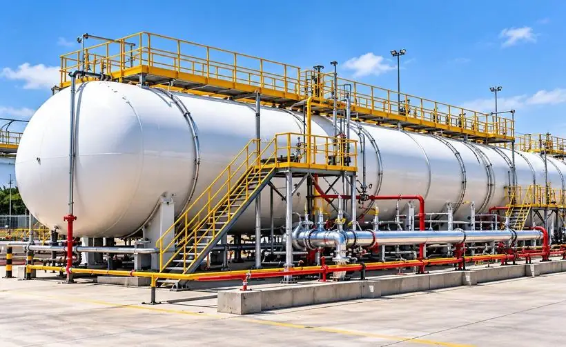
Storage base case
3 × 50 t (110 m³) above-ground bullets, P355GH, design / test 16 / 25 bar.
Transfer
≥ 2 side-channel pumps (30 m³/h each) feed the carousel; LPG compressor (57.5 m³/h) for tanker unloading and tank-to-tank transfer.
Safety
Remote fail-safe shut-off valves, excess-flow valves, breakaway couplings; liquid return prevents vapour lock at the scales.
Critical investment item
Storage volume sets supply autonomy; tank count, pump redundancy and unloading bays are fixed at pre-feasibility.
Carousel size sets plant capacity; stations can be added later
| Stations | Diameter | Cylinders / hour |
|---|---|---|
| 12 | 3,650 mm | 600–700 |
| 18 | 4,800 mm | 900–1,050 |
| 24 | 5,800 mm | 1,200–1,400 |
| 30 | 6,950 mm | 1,500–1,700 |
| 36 | 7,800 mm | 1,800–2,100 |
Ex-proof drive matched to conveyor speed; pneumatic input / output units; an unfinished cylinder is never released. Electronic scales receive the tare via data link and fill to preset weight; ventilation under the carousel removes vapour.
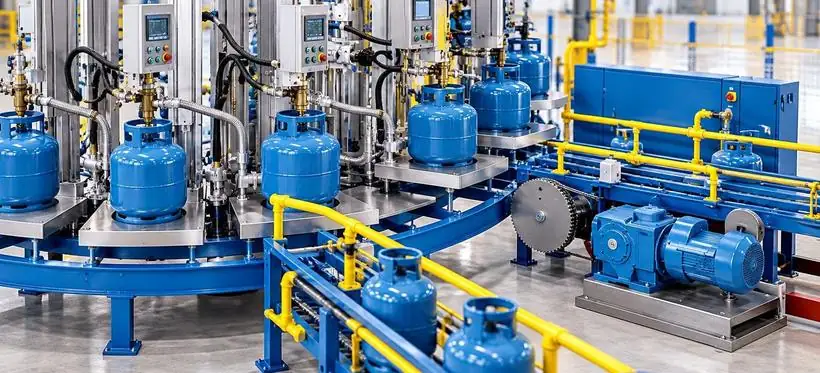
Verification chain before any cylinder leaves the plant

Check weighing
Every cylinder re-weighed at 0.1% accuracy; scales verified with standard weights each shift.

Filling tolerances
Typical: 6–7 kg +0.1/−0 kg · 11–13 kg +0.2/−0 kg · 46 kg +0.4/−0 kg.

Leak detection
Valve, bung and body checked to 2.5 g/h; gas detector or water bath of at least 5 s.

Final safety gate
Rejects segregated; defective cylinders evacuated and gas-freed before any repair.
Rule: overfill detectors never replace check weighing; decanting LPG between cylinders is prohibited.
Detect, isolate and shut down before a leak escalates

Area classification
Outdoor filling point: Zone 1 within 1.5 m, Zone 2 to 16.5 m. Enclosed filling room: Zone 1.

Emergency shut-down
Fail-safe, fire-safe remote valves at hall entry and tank outlets; ESD buttons at manned points.

Gas detection
Ex-proof sensors ≤ 25 cm above floor; alarm trips motors and isolates the zone.

Earthing and bonding
All LPG equipment bonded; resistance to earth ≤ 10 Ω; anti-static floors and footwear.

Ventilation
Open-sided, weather-protected hall; extraction under the carousel removes heavy vapour.

Seismic and lightning
Earthquake sensor trips the plant; lightning protection to EN / NFPA requirements.
ATEX: all electrical equipment in Zones 1 and 2 is ATEX-certified; the control room and MCC sit in the safe area.
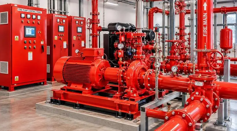
Cooling and suppression sized by the fire-water study and the local fire authority
Deluge rate
Minimum deluge rate on vessels
Design duration
Typical fire-water design duration
Fire pumps
Electric and diesel fire pumps
Monitors
L/min water / foam monitors
Deluge
Fixed deluge over tanks, truck bays and pump / compressor area; auto start linked to ESD.
Hydrants and monitors
Hydrant ring main, monitors and hose cabinets covering all LPG areas.
Filling hall
Sprinklers over the hall and conveyors; 6 kg extinguishers at each station.
Pump house
Fire-water pump house located at a safe distance from LPG storage.
Turnkey scope matrix, finalised to cylinder mix, capacity and automation level

Bulk storage
3 × 50 t bullets, level gauges, relief valves; EN 13445 / PED, deluge-protected

LPG transfer
Side-channel pumps, compressor, tanker hoses; breakaway couplings, ESD valves

Handling
Chain conveyors, telescopic loaders, palletisers; up to 1,200 cyl/h per line

Filling
Carousel, electronic scales, input / output units; tare data link, 10 g accuracy

Quality control
Check scale, correction scale, leak detector / pool

Finishing
Shrink-sleeve sealing, cap fitting, coding

Maintenance
Evacuation unit, valve changing, hydrotest, washing; hot work outside hazardous zones

Safety / utilities
Gas detection, fire pumps, air compressor, 150 kVA genset, MCC; ATEX certified
From bulk LPG receipt to cylinder dispatch on one site
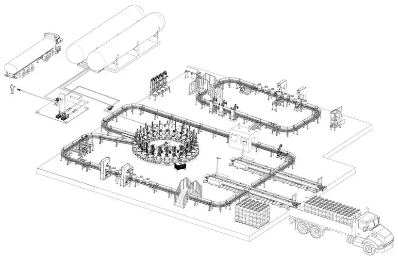
- 01
Tanker unloading
- 02
Bulk storage tanks
- 03
Pump and compressor station
- 04
Filling carousel
- 05
Check and correction scales
- 06
Leak detection and valve sealing
- 07
In-line filling loop (stand-alone scales)
- 08
Palletising and truck loading
Typical arrangement. Final plot plan follows the site survey, HAZOP and local safety distances (filling area ≥ 15 m from public roads, one-way truck traffic).
A filling plant’s licence to operate depends on its procedures as much as its capacity

ITP / FAT plan
Inspection and test plan; FAT at supplier works, SAT on site.

Scale calibration
Filling and check scales verified against standard weights every shift.

Filling records
Tare, fill and check-weigh data stored in the plant database.

Cylinder management
Inspection, requalification, re-valving and scrapping per national rules.

Emergency procedures
ESD tests, fire drills, gas-freeing and evacuation procedures.

Digital plant
Remote monitoring, production dashboard, barcode / RFID traceability (option).
Output: a licensed, auditable filling operation with records ready for the regulator and third-party inspection.
EPC+F / turnkey approach from pre-feasibility to trial filling
Pre-feasibility
Demand, cylinder and valve mix, site data, storage size
Technical proposal
Layout, equipment list, safety concept, CAPEX / OPEX
Engineering and procurement
Detailed design, vendor selection, FAT, shipment
Construction and commissioning
Civil, mechanical and electrical works, SAT, trial filling, training
Quotation inputs
- 01
Cylinder sizes and valve types (top / side filling)
- 02
Target throughput: cyl/h, per shift or t/year
- 03
Bulk storage need and LPG supply route
- 04
Site plot plan, access roads, utilities
- 05
National codes and licensing authority
- 06
Automation: manual, semi- or fully automatic
One contract for the plant and its funding
Financing instruments
Export credit agency (ECA) backed buyer credit, commercial bank and development finance facilities.
Supplier credit
Deferred payment on equipment as part of the financing package.
Path to financial close
Financial model → term sheet → lender due diligence → financial close.
Single counterparty
ASKAY delivers the facility and arranges the financing package under one contract.
Financing terms are subject to lender credit approval and country risk assessment.
Next steps
The right plant concept, robust safety systems, controlled filling quality and EPC+F financing.
- 1Confirm cylinder mix, throughput and site data
- 2Prepare vendor RFQ package and plant layout
- 3Develop budget proposal and financing structure